

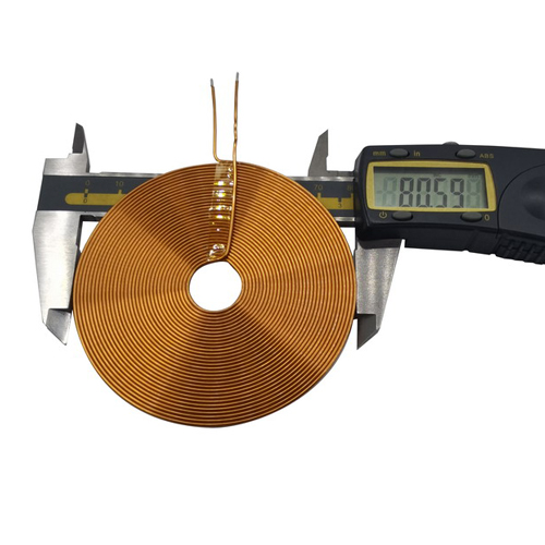
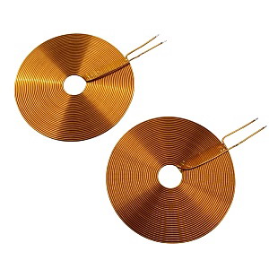
The medical inductor coil charging solution can charge various wireless chargers with a conversion rate of over 80%. Medical inductive coils are divided into transmitting coils and receiving coils. The transmitting coil is generally thick, with a thickness between 1mm-3mm. The back is a magnetic separator, and the top is a flat wound copper coil. Multiple thin copper wires are wound and installed on a composite protective cover. The receiving coil is very thin, usually about 1mm thick, and the back is also a magnetic separator. The coil is flat rolled, flattened, or directly made of soft PCB. The medical inductor coil has passed the QI international wireless charging standard certification, with low temperature and high safety. The material selection for medical sensors mainly includes the following types.
1. Ferrite medical inductor coils and iron core medical inductor coils
The inductance of a medical inductor coil is directly related to the presence or absence of a magnetic core. Inserting ferrite cores into hollow medical inductors can increase inductance and improve the quality factor of medical inductors.
2. Copper core medical inductor coil
Copper core medical inductors are widely used in the ultra short wave range. Changing the orientation of the copper core in the medical inductor coil by rotating it is very convenient and durable.
3. Single layer medical inductor coil
The single-layer medical inductor coil is wrapped with insulated wire one by one around a paper tube and a rubberwood frame. For example, the medical inductor coil of the waveform antenna in a transistor radio.
Medical inductive coils first choose the principle of electromagnetic induction, which ends energy transmission through intermittent energy coupling of the coil. When the system is working, the input terminal converts AC mains power into DC power through a full bridge rectification circuit, or directly supplies power to the system with 24V DC power. After passing through the power processing module, the output DC power is converted into high-frequency AC power through the inversion of a 2M active crystal oscillator and supplied to the primary winding. By coupling the energy of two induction coils, the receiving conversion circuit converts the current output by the secondary coil into direct current to charge the battery.

服務(wù)熱線:
18825827211